Sending GPS data over LoRa for HAB tracking
June 11, 2023
Image source: a wonderful creation by Dall-E
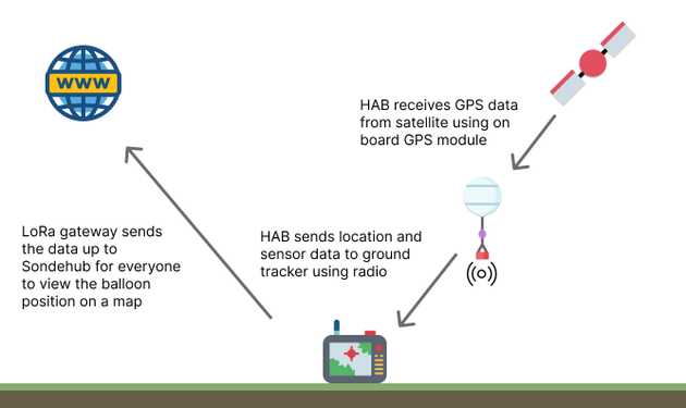
This post carries on from my previous post on tracking High Altitude Balloons (HAB) using LoRa to send location data to a LoRa gateway. That post set up a LoRa transmitter (an ESP32 board) to send a fake UKHAS telemetry string to be received by a stationary LoRa gateway (a Raspberry Pi 4). This post will take it a step further and use a GPS receiver to get real, accurate GPS data and send that over LoRa, to be received by the same gateway device.
As mentioned before, the UKHAS telemetry string is what the LoRa gateway software recognises as a valid string to be send to Sondehub, which is a web app to show real-time HAB tracking events from all over the world. The end goal is to launch a balloon to be tracked on Sondehub.
This post contains
High level component setup
As the gateway receiving device will be exactly the same hardware and software as my previous post (a Raspberry Pi 4), I won’t go into much detail about that config in this post. The transmitting device will be a little different from my previous posts though.
I previously used an ESP32 board to connect a LoRa module and send data out, but for this post I used a Raspberry Pi Pico instead. I wanted to change things up a bit, and experiment using a Raspberry Pi Pico with Arduino IDE, which turned out to work really well. The Pico is a little smaller, much faster, and actually cheaper than the ESP32.
Of course, the Pico will need to use a LoRa module to transmit data to the gateway, similar to what I did with the ESP32. There will also be a GPS receiver connected to the Pico this time, which will get coordinates and altitude data to send to the gateway.
Choosing a GPS receiver
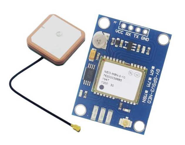
There are a load of GPS receivers out there, and I tested a few out. I started by getting the GY-NEO6MV2 GPS Module which was only £4 but the quality was awful. I received a GPS signal once for about 10 seconds, which wasn’t very accurate. I then tried a few more times over multiple days to get the signal again but with no luck.
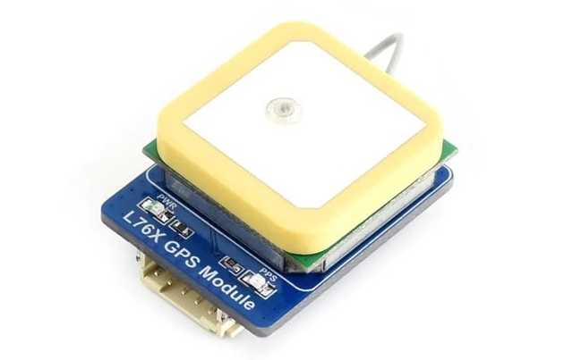
At the same time I also purchased a L76X Multi-GNSS Module module which was a little more expensive at around £20. This one seemed to be better quality and received a GPS signal within 1 minute, but the coordinates I received was about 5 miles away from my real location. I tried this on multiple days with good weather conditions and waited ages to see if something would stabalise, but also no luck.
I sent both units back as I considered them either faulty or too bad quality for purpose.
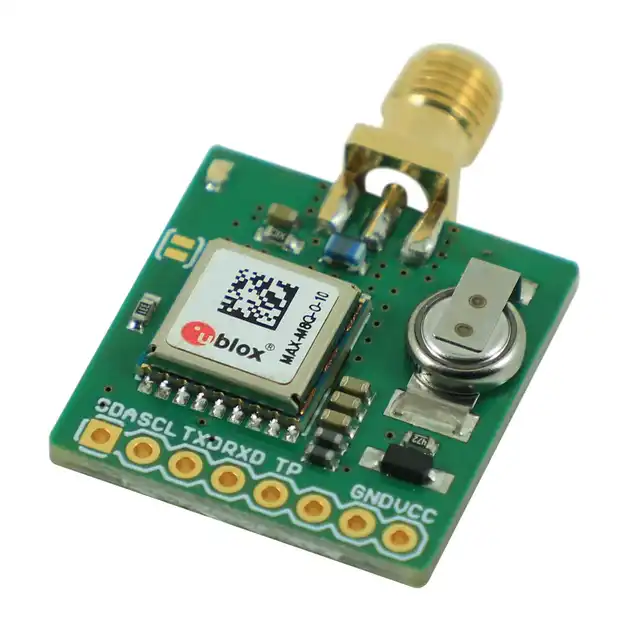
One other consideration when selecting a GPS tracker is that most standard ones don’t track above 18,000 meters. This is important because a HAB will likely go beyond this altitude. There are some specialist units that claim to be able to track above this altitude though, and one such unit is the uBLOX MAX-M8Q Breakout for Active Antennas. I decided this would be good for the HAB fight as the higher altitudes are specified in the product description, and also the fact that an active antenna is used means the antenna doesn’t need to be constrained inside the payload box on a HAB - the antenna can be external to receive the best possible signal.
Using the UBlox GPS module
I started by getting the GPS module configured to send coordinates to the Pico where I could see the data in the serial monitor.
Reading GPS data directly from the module
The GPS data can be read directly from the module by reading from the UART connection. For example:
#include <SoftwareSerial.h>

SoftwareSerial gpsSerial(1, 2);

void setup() {
  gpsSerial.begin(9600);
}

void loop() {
  while(gpsSerial.available()) {
    byte gpsData = gpsSerial.read();
    Serial.write(gpsData);
  }
}
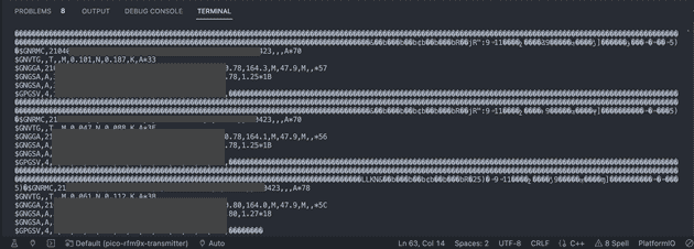
This would output something like the following:
The data there is raw GPS data strings in a language called NMEA (National Marine Electronics Association), which is widely used in GPS modules all over the world. It’s not very readable, but it can be parsed to pull out the desired information we want. This can be done manually, but it requires a lot of work. Luckily, there’s a library to do it for us!
Using TinyGPS++ to parse GPS data
There is one library called TinyGPS which should be avoided as it’s very old and not maintained anymore. The same creator of that library went on to develop a second version called TinyGPS++ which looks to be widely used with almost 1k stars on GitHub at time of writing.
While being very simple to use, this library gives you everything you need to parse GPS data and get all sorts of useful data out of the NMEA strings shown earlier.
The problem with the delay() function when parsing GPS data
I started by using a simple TinyGPS++ example to grab data and show in the serial monitor, however I received all zero values. Here was the code:
// ...

void loop() {
  // While there are characters to come from the GPS
  while(gpsSerial.available()) {
    //This feeds the serial NMEA data into the library one char at a time
    gps.encode(gpsSerial.read());
  }

  //Get the latest info from the gps object which it derived from the data sent by the GPS unit
  Serial.println("Latitude:");
  Serial.println(gps.location.lat(), 6);
  Serial.println("Longitude:");
  Serial.println(gps.location.lng(), 6);

  // Add a 1 second delay so the serial monitor can be observed easier
  delay(1000);
}
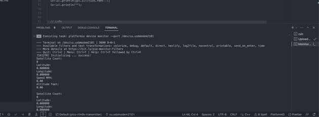
The idea as to show basic data, with a 1 second delay. Without the delay, the serial monitor would be flooded with the data stream and after a minute or so tends to slow down my laptop and makes it hard to read the values. The delay() function is often used in beginner tutorials to help with this very problem because it’s easy to use. However when used in this situation, the output of the GPS data looks like this:
A quick Google found this answer on the Arduino forum which explains that the data can’t be read correctly with the delay function in place, because the serial buffer is populated with a number of characters per second, which are missed from being read during the subsequent loop of the program. This is because the delay is a blocking function so it prevents the program from doing anything during the delay time.
Our program needs to be able to do multiple things at the same time, and the delay function will stop this from being achieved because of the asynchronous process of us grabbing the GPS data, and using that data to send over LoRa without one relying on the other to complete.
The solution to the delay() function issue - using millis()
The millis() function returns the number of milliseconds that have passed since the program was fired up on the board. With that number being a constant/anchor point, we can use some simple maths to create our own, non-blocking delay:
// ...
long lastDisplayTime = 0;

void loop() {
  // While there are characters to come from the GPS
  while(gpsSerial.available()) {
    //This feeds the serial NMEA data into the library one char at a time
    gps.encode(gpsSerial.read());
  }

  // Calculate when every 2 seconds have passed since the program started, and reset the `lastDisplayTime` flag each time
  if (gps.location.isValid() && (millis() - lastDisplayTime >= 2000)) {

    //Get the latest info from the gps object which it derived from the data sent by the GPS unit
    Serial.println("Latitude:");
    Serial.println(gps.location.lat(), 6);
    Serial.println("Longitude:");
    Serial.println(gps.location.lng(), 6);

    lastDisplayTime = millis();
  }
}
This means that we aren’t observing the data stream on every loop, and it also gives us control over the timings which will be useful for the next part of the program which is to use that data to send over LoRa.
Sending the GPS data over LoRa radio
With the GPS data being processed every 2 seconds, we can integrate the LoRa communication part. I’d previously used the arduino-LoRa library in other posts to send/receive LoRa, but for this post I decided to use a different library called RadioLib. They perform a similar job, but the RadioLib library has much wider support for different types of transcievers, is currently under active development, and has a huge amount of interest on GitHub.
After a bit of experimenting I created this program:
#include <Arduino.h>
#include <RadioLib.h>
#include <TinyGPS++.h>
#include <SoftwareSerial.h>

// LoRa
SX1278 radio = new Module(17, 20, 6, 21);

// GPS
int RXPin = 1;
int TXPin = 0;
int GPSBaud = 9600;
TinyGPSPlus gps;
SoftwareSerial gpsSerial(RXPin, TXPin);

long lastDisplayTime = 0;
float lat = 0;
float lng = 0;
float alt = 0;
float speed = 0;

// General
boolean showOnSondehubMap = false;
char callSign[] = "CALL0135";
int counter = 0;

void transmitLocation(char* data);
char * getTimeStr(TinyGPSTime &t);

void setup() {
  delay(5000);
  Serial.begin(9600);

  // GPS
  gpsSerial.begin(GPSBaud);

  // LoRa
  Serial.print("[SX1278] Initializing ... ");
  int state = radio.begin(433);
  radio.explicitHeader();
  radio.setBandwidth(125.0);
  radio.setSpreadingFactor(7);
  radio.setCodingRate(7);
  radio.setCRC(true);

  if (state == RADIOLIB_ERR_NONE) {
    Serial.println(F("success!"));
  } else {
    Serial.print(F("failed, code "));
    Serial.println(state);
    while (true);
  }
}

void loop() {
  while(gpsSerial.available()) {
    gps.encode(gpsSerial.read());
  }

  if (gps.location.isValid() && gps.altitude.isValid() && gps.speed.isValid() && (millis() - lastDisplayTime >= 2000)) {
    Serial.println("Satellite Count:");
    Serial.println(gps.satellites.value());
    Serial.println("Latitude:");
    Serial.println(gps.location.lat(), 6);
    Serial.println("Longitude:");
    Serial.println(gps.location.lng(), 6);
    Serial.println("Speed MPH:");
    Serial.println(gps.speed.mph());
    Serial.println("Altitude Feet:");
    Serial.println(gps.altitude.feet());
    Serial.println("");

    lat = gps.location.lat();
    lng = gps.location.lng();
    alt = gps.altitude.feet();
    speed = gps.speed.mph();

    char timeString[32];
    if(gps.time.isValid()) {
      sprintf(timeString, "%02d:%02d:%02d", gps.time.hour(), gps.time.minute(), gps.time.second());
    } else {
      sprintf(timeString, "%s", "00:00:00");
    }

    char locationString[256];
    sprintf(locationString, "%s%s%s%i%s%s%s%f%s%f%s%f%s%f", showOnSondehubMap ? "$$" : "", callSign, ",", counter, ",", timeString, ",", lat, ",", lng, ",", alt, ",", speed);

    transmitLocation(locationString);

    counter++;
    lastDisplayTime = millis();
  }
}

void transmitLocation(char* data) {
  Serial.println("Transmitting packet ... ");
  Serial.println(data);
  int state = radio.transmit(data);

  if (state == RADIOLIB_ERR_NONE) {
    // the packet was successfully transmitted
    Serial.println(F("Packet transmitted ok!"));

    // print measured data rate
    Serial.print(F("[SX1278] Datarate: "));
    Serial.print(radio.getDataRate());
    Serial.println(F(" bps"));

  } else if (state == RADIOLIB_ERR_PACKET_TOO_LONG) {
    // the supplied packet was longer than 256 bytes
    Serial.println(F("too long!"));

  } else if (state == RADIOLIB_ERR_TX_TIMEOUT) {
    // timeout occurred while transmitting packet
    Serial.println(F("timeout!"));

  } else {
    // some other error occurred
    Serial.print(F("failed, code "));
    Serial.println(state);
  }
}
The GPS code is what I described earlier, and the LoRa code is taken from the example section on the RadioLib repo. This updates some global variables (lat, lng etc…) to hold the latest GPS values, and uses them to create a UKHAS telemetry string which will be received by the gateway.
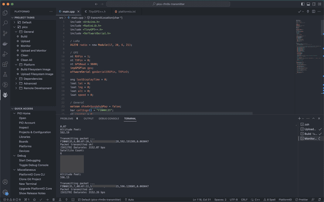
The end result should see the serial monitor outputting something like:
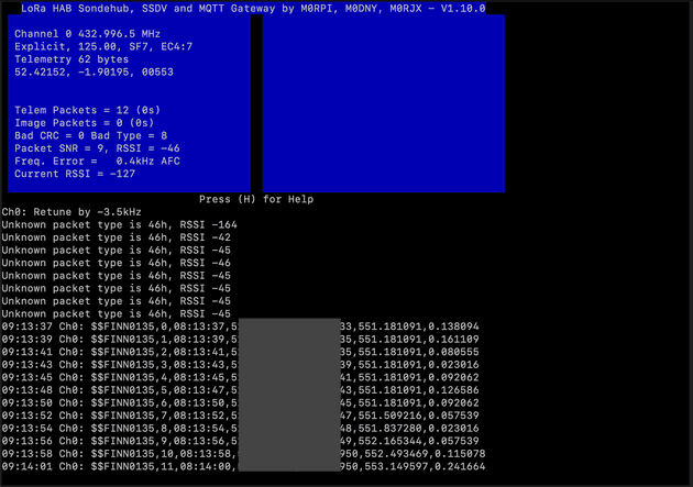
With the data sending from our attached LoRa module, and with correct LoRa configuration, the gateway is able to receive the GPS data:
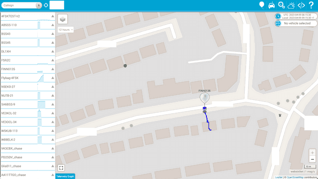
And finally that accurate GPS data is sent to Sondehub to be displayed on the map:
The wiring configuration
Here’s the wiring configuration for the transmitting device (the receiving gateway configuration is covered in my previous post):
RFM9x module to Raspberry Pi Pico
| RFM9x module | Raspberry Pi Pico |
|---|---|
| VCC | 3.3V (pin 36) |
| GND | GND (pin 33) |
| NSS/CS | G17/pin 22 |
| NRESET | G6/pin 9 |
| DIO0 | G20/pin 26 |
| DIO1 | G21/pin 27 |
| SCK | G18/pin 24 |
| MISO | G16/pin 21 |
| MOSI | G19/pin 25 |
It’s worth noting here that the SPI pins for the Pico are using the defaults as defined in the arduino-pico core that I’m using. I made another post recently on how to use the Raspberry Pi Pico with Arduino IDE which explains in more detail about that library, but essentially the SPI pins on the Pico can be configured to be almost any pin on the board. The arduino-pico core is the software that allows the Pico to interface with the Arduino IDE, and has it’s own definitions for the SPI pins, which I have outlined above in the table.
GPS module to Raspberry Pi Pico
| GPS module | Raspberry Pi Pico |
|---|---|
| VCC | 3.3V (pin 36) |
| GND | GND (pin 38) |
| RX | G0/pin 1 |
| TX | G1/pin 2 |
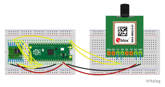
Here’s a Fritzing (excuse the weird sizings on the GPS module and lack of breakout board on the LoRa module):
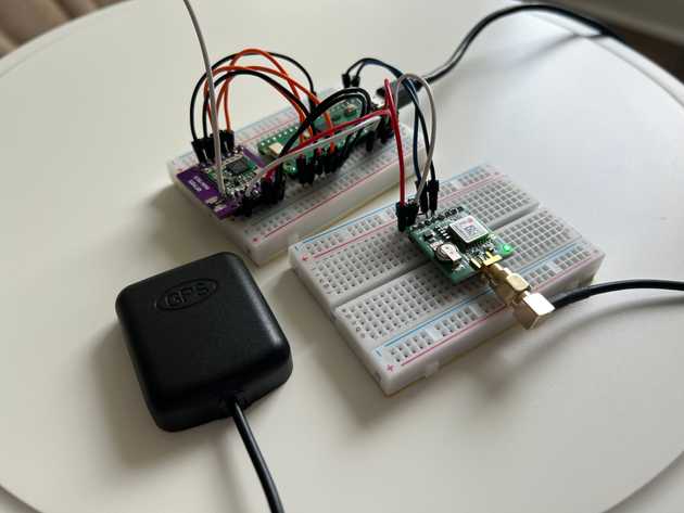
And a photo of the final wiring:
Senior Engineer at Haven
