Programming the Raspberry Pi Pico in Arduino IDE on a Mac
June 01, 2023
Image source: a pretty bad creation by Dall-E
I have been experimenting with ESP32 WROOM and Raspberry Pi 4 lately, spending a little more time in Arduino IDE and less time using Thonny with my Raspberry Pi Pico. I noticed how much more of a pleasant experience Arduino IDE is, so decided to start using my Pico in Arduino IDE. It didn’t go as smoothly as I’d have liked, so I am dumping my learnings here.
Selecting the Raspberry Pi core
Out of the box, Arduino IDE doesn’t support all dev boards. Board manager software is required to be installed to Arduino IDE in order to give such support. One of the more popular board managers is the arduino-esp32 core which is used by many to program the ESP32 boards using Arduino IDE. Others include the teensy core and adafruit-arduino core.
The same goes for a RPi Pico, but with the Pico there are two major players - the ArduinoCore-mbed and arduino-pico. The arduino-pico seems to be the more popular and friction-less solution after doing some digging, so that’s what I chose, even though it’s the unofficial solution.
Adding the board manager URL to Arduino IDE
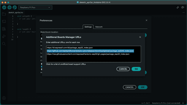
Start off by adding the arduino-pico board manager JSON file to Arduino IDE. Go to File > Preferences > Additional boards manager URLs and add the URL:
https://github.com/earlephilhower/arduino-pico/releases/download/global/package_rp2040_index.jsonInstalling the board in the board manager
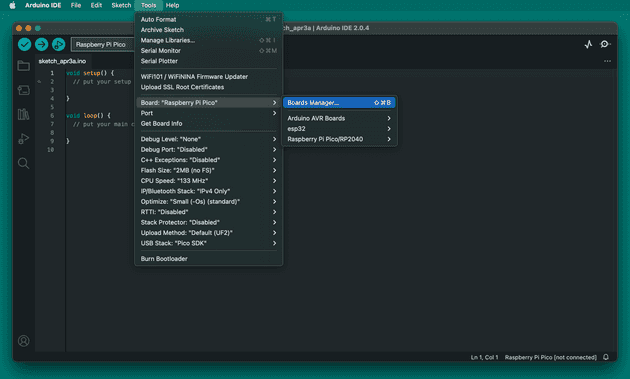
Now Arduino IDE has visibility of what board we want to install, we can go ahead and initiate the installation. Go to Tools > Board > Board Manager:
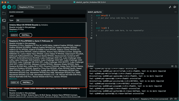
And then type pico in the search bar to view the Pico board packages:
You’ll see the official Arduino Mbed OS board in the list probably, but don’t install that one. In fact, I recommend uninstalling it if you have it installed already, as it helps keep things less confusing when seeing various options in the IDE.
Proceed to install the Raspberry Pi Pico/RP2040 board package.
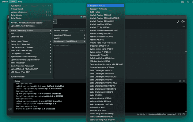
You can then select the Pico board from the boards menu:
Uploading a simple sketch to the Pico to begin with
The Pico doesn’t have the correct firmware installed by default which allows the usage of Arduino IDE features. However, the firmware is automatically installed along with the first sketch we upload. The first sketch needs uploading a little differently though.
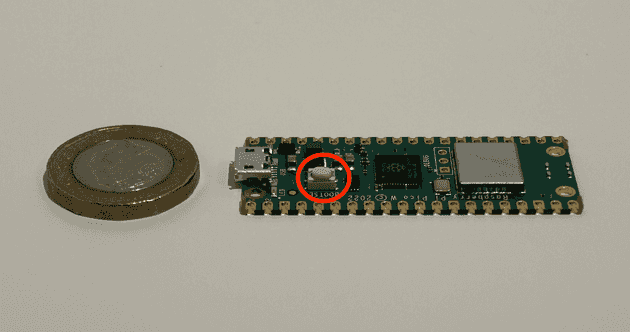
To upload the initial sketch, unplug the Pico from your machine, press and hold the BOOTSEL button on the Pico, and keep the button held while you plug the USB into your machine:
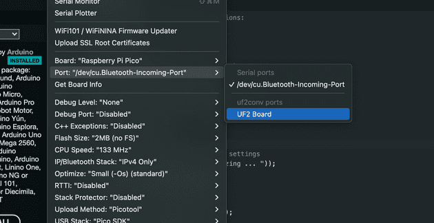
This sets the board up to receive bootloader instructions. You’ll notice the Pico now appears as a USB drive on your machine, and the port in Arduino IDE shows a UF2 board:
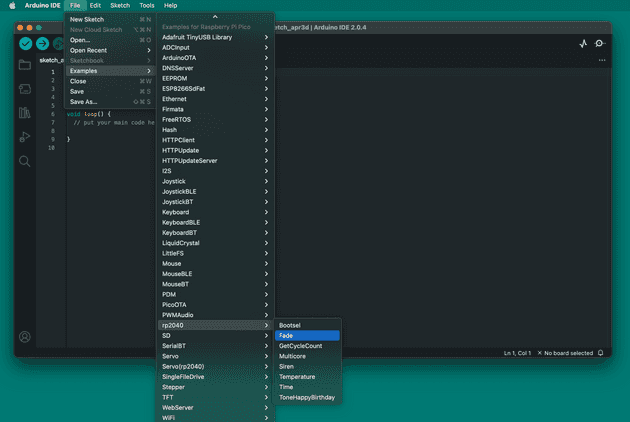
You should start by uploading a simple sketch, such as the example “Fade” sketch. I found this most helpful as I’d spent ages trying to get my proper sketch installed only to realise that you can’t debug using Serial output like with ESP32 or Arduino. By installing a simple sketch which you’re confident should work, you’re eliminating your own code issues while getting past the first step:
Ensure the Serial port is connected (in my case it is /dev/cu.Bluetooth-Incoming-Port Serial Port), and not the UF2 port, and then upload the sketch. Once uploaded, you’ll see the LED on the Pico fading in and out, and the success message in Arduino IDE, confirming the first upload was a success.
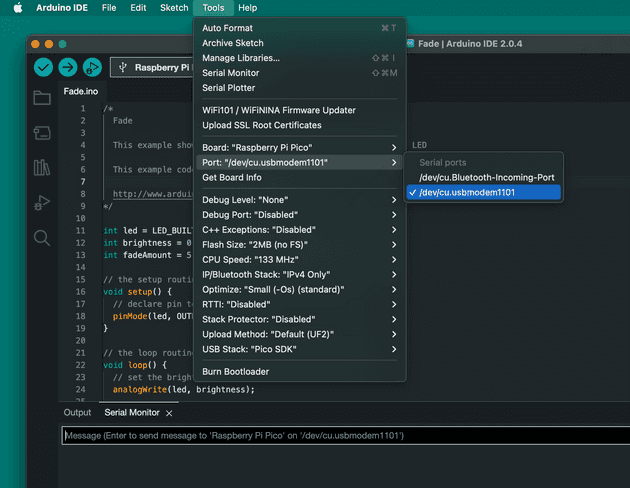
Once that first sketch is installed, the Pico will have the Arduino IDE firmware installed, and you will be able to select the proper port (in my case, /dev/cu.usbmodem1101) which allows for viewing Serial messages over USB from the Pico:
As the firmware is installed now, you’ll no longer need to hold down the BOOTSEL button, unless there is some sort of error or you’re unable to upload a sketch in future, in which case running through the BOOTSEL method is required.
Note: this will flash the Pico and remove all existing data/programs that you have installed, so be sure to back up anything you don’t want losing.
Seeing Serial port data and debugging
You’ll notice when running another example such as the Temperature sketch, you’ll be able to see Serial output (as long as you have installed your first sketch using BOOTSEL method above, and have the correct Port selected).
This is great for seeing the output from your program while in development, but you may also want to debug your Pico to see when errors occur. At the moment when the Pico errors, it will no longer function in Arduino IDE, and you won’t see the errors in the Serial output like with ESP32s and the like. There are a couple of solutions to allow debugging on a Pico, but they aren’t a one-click install:
- pico-debug allows you to debug by installing additional firmware on the Pico.
- picoprobe installs debug software on one Pico, which connects to another Pico to alow debugging over a USB -> SWD and UART bridge.
Using SPI communication with arduino-pico
There’s a lot of considerations when programming a Pico with Arduino IDE, and one of them is how the Pico communicates with other devices/modules. I have spent most of my time using the SPI interface, so I’ll briefly explain how to use SPI.
The Pico does have default SPI pins (see here and here), however these default pins differ depending on what firmware the Pico is using. For example, if running the arduino-pico core (as I have shown in this post), the default pins are:
| SPI channel | DIO Pin |
|---|---|
| MISO | DIO16 |
| MOSI | DIO19 |
| CS | DIO17 |
| SCK | DIO18 |
Although the default pins can be used, there’s also the option to set any pin to be an SPI pin. This is a feature of newer dev boards like the Pico, giving more customisation. Again, this must be handled differently depending on what firmware you’re running. There’s some great docs for arduino-pico about SPI.
This is done in arduino-pico by setting the pins in the setup() function:
void setup() {
  SPI.setRX(10);
  SPI.setTX(11);
  SPI.setCS(13);
  SPI.setSCK(12);
  SPI.begin(true);
}
Where MISO (Master Input, Slave Output) is RX and MOSI (Master Output, Slave Input) is TX.
Senior Engineer at Haven
