Using LoRa for communication between ESP32 and Raspberry Pi
May 03, 2023
Image source: a wonderful creation by Dall-E
Following on from my previous posts about my journey into learning about high altitude balloons (HAB), I think one of the most crucial aspects of HAB is tracking. Without the balloon tracking you’re basically sending up an expensive, fancy balloon never to be seen again. Rather than diving straight into a full solution, I decided to start simple and get a data string transmitted between two devices.
There are different methods to transmitting data between two microcontrollers, which includes the usual Bluetooth, WiFi, etc, but those can only transmit over a very short distance. There are some alternative solutions which are popular among the HAB community, and those include using radio - namely RTTY and LoRa.
RTTY is a method of using a radio transmitter to send radio pulses between two frequencies. The difference in frequencies are interpreted at the receiving end kind of like how machines process digital data, with up and down signals. This is a good resource for learning about RTTY if you’re interested. RTTY seems to be an older technique, and can be more complex in terms of setting up the receiving end of the frequency modulation, as explained here.
LoRa on the other hand, is a different technique to RTTY, and seems to be the preferred way to track a HAB because of it’s relative ease of use, and apparently much longer (up to 15 km) potential transmission distance (based on similar size/cost of transceiver component) compared to RTTY. LoRa is patented and proprietary, so you must use transceivers that support LoRa, instead of a usual radio transmitter.
I decided to pursue LoRa as a method of transmitting data, so this post will cover what I learned, and how I set up a (really) basic LoRa transmission between two transceiver modules.
This post contains
What LoRa devices can you use for high altitude balloons
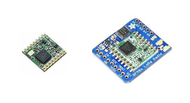
I spent some time looking into options for using LoRa. All the popular LoRa modules I found are transceivers, which is where the module can both transmit and receive data (as long as sender and receiver are on the same frequency). The LoRa modules are tiny, and can either be purchased as a standalone module, or as part of a breakout board. Here’s what they both look like:
There are loads of breakout boards such as this popular Adafruit one and this popular SparkFun one (which is embedded to an ESP32 module), but I didn’t want to go for these. Instead I wanted to proceed with the standalone module as I like the idea of having more flexibility - allowing me to add to my own breakout board or connect directly, depending on my requirements.
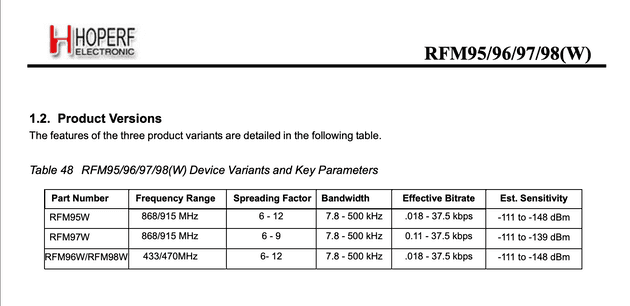
There are only a few readily available types of standalone modules to chose from, especially here in the UK. I ended up getting two modules from Uputronics, which is a UK based company. I chose the HopeRF RFM98W which are £9.50 each at time of writing, which is cheaper than other places I could find. I purchased the RFM98W because it operates at 433mhz frequency.
Choosing the right frequency of LoRa module
One important consideration when purchasing a LoRa module (breakout board or standalone) is the frequency. There are four different models of HopeRF’s LoRa modules, each with a specific frequency:
This is important because the frequency you chose depends on what part of the world you live. Most countries have set frequencies that are legal for use by amatuer users because of the potential for interferrence with things like emergency services radio and other critical systems. Here in the UK we are able to use the 433mhz and 868mhz frequencies. According to Ofcom, “most domestic alarm systems in the UK used the 433 MHz band on cost grounds but this has become increasingly prone to interference from other wireless devices such as baby monitors … there has therefore been a marked migration to 868 MHz in recent years”.
Point to point vs a LoRa wide area network
Transmission of LoRa radio can be categorised into point to point and low power wide area network (LPWAN). I’ll cover LPWAN (and the LoRaWAN network protocol) in a future post, but for now I’ll start with the more simple point to point method of using LoRa.
Using LoRa point to point is essentially having two LoRa modules of the same frequency/model. One is set to transmit data and one is set to receive data. The modules don’t act independently of course - they still need to be attached to something that runs a program and controls the data, such as a microcontroller or small computer.
Using point to point LoRa communication is something actively used right now to aid with things like farming and manufacturing because of it’s low cost and long distance transmission in areas that can have no WiFi or cellular data available.
Getting started with HopeRF RFM98 LoRa module
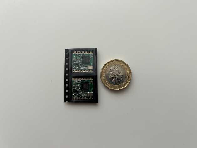
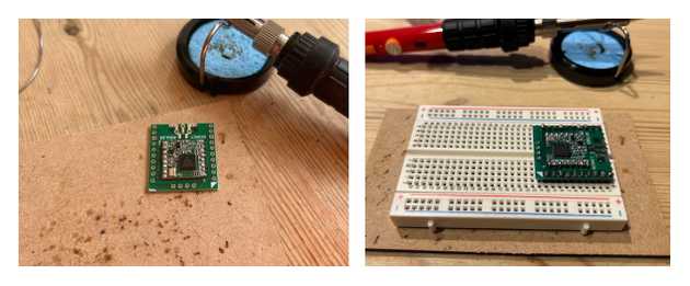
Once the RFM98 modules were delivered, I realised how incredibly small they are:
So small, that they don’t fit on a breadboard like most other components because the header pin spacing is too tight. People have come up with some pretty nasty looking solutions to use the bare modules on a breadboard though, as shown in this forum post. I did try some of these solutions, but alas my soldering skills were not yet up to scratch so I ended up making a proper mess of one of the boards. I decided to look for a more suitable, permanent solution.
Finding a RFM9x adapter board
My end goal was to get the RFM module usable with a breadboard (and eventually a soldered PCB). I found this great video from the guy over at mobilefish.com which takes a breadboard friendly adapter board made for another component entirely, and repurposes it.
There’s also this nice looking FlexyPin adapter which I think is a pretty new approach to securing small modules to breasboard friendly boards, however it didn’t come with the pins, seems like a huge faff, and got bad reviews.
I found loads of adapter boards for LoRa modules but they were all shipped from Australia and the US, where the shipping alone was £20-£30 for a £1.50 adapter board.
Before beginning to create a monstrosity of a board setup without an adapter, I decided to have one more look online to see if I could find any thing else, and I found some! I eventually came across tindie.com. I found a couple of suppliers which were located in the UK and France, so I bought 3 boards from each supplier with a total cost of £12 including shipping - perfect.
Attaching the RFM9x module to board to the adapter
With the Tindie adapter boards delivered, I began soldering the RFM98 module to the adapter, and then the adapter to the header pins. The boards were made to great quality, which along with using some good soldering flux paste, meant the soldering was pretty straightforward. It took a little while to solder the first module, but the second one only took a couple of minutes when I was in the swing of it.
Finally, one great thing about these adapter boards is that they have a dedicated area to fix an antenna. I went for the easiest antenna method for my first attempt with point to point LoRa, which was to use a wire antenna.
There’s a lot to cover on the topic of antennas, and I’ll leave that for another post. For now though, the important part is the length of the antenna. There are resources to explain the math behind it but specifically for the 433mhz module I am using, the wire needs to be 17.3cm in length, ideally pointing straight upwards away from the board.
Choosing a library to interface with LoRa modules
I’m comfortable writing code, but when you start getting into the weeds of low-level programming of LoRa modules, it starts to get a bit involved. Writing this level of code in C++ isn’t my forte, so I wanted to look for libraries that can be used to abstract the complexity out in to easy to use API.
I started by doing a search on GitHub for repos containing RFM9x sorted to show the most popular first. This lead to finding a few great contenders for getting started. It’s worth bearing in mind that LoRa only started appearing mainstream around 2010-2015, and there have been a load of changes in the last 10 years. Finding a currently maintained and popular library is difficult, so be sure to take a look around yourself if you’re interested. The ones which looked great for me at time of writing:
- RadioLib - seems to have amassed an incredible amount of GitHub stars in the short time it’s been around, supports a wide range of boards, and has great documentation.
- SX12XX Library - also seems popular, and is coincidentally maintained by the same guy who I purchased my RFM9x adapter boards from. The RFM9x modules I am using here all use the SX1276 chip, which is where this library gets it’s name.
- arduno-LoRa - very popular and is widely referenced in almost all guides/tutorials online, possibly because of it’s really simple implementation. Note that this doesn’t just cover the Arduino board - the Arduino references the IDE which is widely used as an IDE for almost all microcontrollers such as those made my Raspberry Pi, SparkFun and everyone else.
- adafruit-circuitpython-rfm9x - also very popular, but not made specific for microcontrollers like the above libraries. Instead, this is made for GNU/Linux based systems, such as the Raspberry Pi 4 - a mini computer.
There are a few more popular libraries not mentioned above, but they are solely used to interact with LoRaWAN which will be covered in a future post.
Deciding which boards to attach the LoRa modules to
The LoRa modules need to each be connected to separate processing boards on which to load the software to perform the magic and interact with the modules themselves. The easiest solution would be to select two of the same boards - i.e. two Raspberry Pi Pico boards, or two ESP32 boards. However as I’m using this project to learn as much as I can, I decided to set up communication between an ESP32 WROOM and a Raspberry Pi 4.
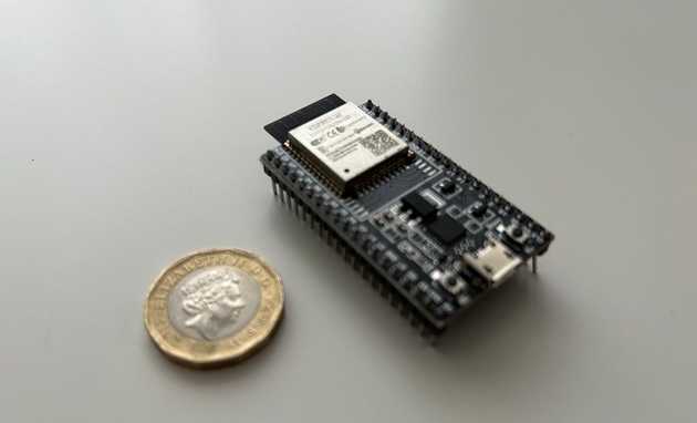
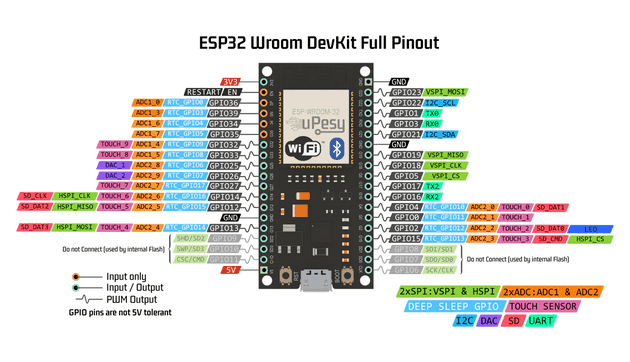
The ESP32 is a low power, popular microcontroller dev board with WiFi and bluetooth baked in, and a load of pins to add new modules and functionality:
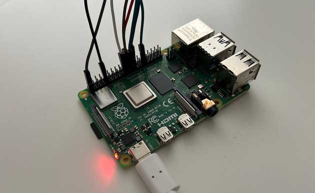
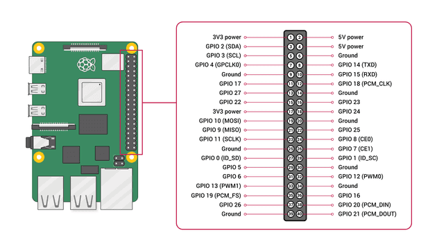
The Raspberry Pi 4 is a full machine with a fair amount of processing power for such a small device. It runs a version of linux as standard, so can do pretty much anything from serve websites to control IoT at home, including using LoRa modules:
The choices of hardware allow the usage of two different libraries:
- The ESP32 will use arduno-LoRa to interface with one of the RFM98 modules send data out
- The Raspberry Pi 4 will use adafruit-circuitpython-rfm9x to interface with the other of the RFM98 modules to receive the transmission from the ESP32
Configuring point to point communication between the two RFM9x modules
I’ll cover each board separately.
Using arduino-LoRa with ESP32 board
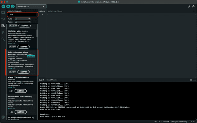
This will be used for sending data out. Reading the instructions is the best place to start, but the first thing to do is install the library in the Arduino IDE:
Once installed, go to the library examples folder on GitHub and copy the LoRaSender.ino script to a new sketch.
There are a couple of things that may need changing. First, the frequency needs to be configured to match that of the LoRa modules being used. I am using 433mhz, so my sketch updates to:
if (!LoRa.begin(433E6)) {
  Serial.println("Starting LoRa failed!");
  while (1);
}
Second, I configured my pins in a different way than the default:
LoRa.setPins(4, 2, 26);I also adjusted my message, so my final sketch is below:
#include <SPI.h>
#include <LoRa.h>

int counter = 0;

void setup() {
  Serial.begin(9600);
  while (!Serial);
  LoRa.setPins(4, 2, 26);
  Serial.println("LoRa Sender");

  if (!LoRa.begin(433E6)) {
    Serial.println("Starting LoRa failed!");
    while (1);
  }
}

void loop() {
  Serial.print("Sending packet: ");
  Serial.println(counter);

  LoRa.beginPacket();
  LoRa.print("A message from ESP32 - ");
  LoRa.print(counter);
  LoRa.endPacket();

  counter++;

  delay(10000);
}
Wiring the RFM9x module to the ESP32 microcontroller
The final thing to do is wire up the RFM9x module to the ESP32. My ESP32 module could be an older version, or at least a slightly different version than the more popular one, because the pinout diagram for mine is a little hard to find:
The LoRa modules communicate with the boards they’re attached to using SPI ports (a different and much faster protocol than the UART which is more popular during beginner tutorials). I originally tried using HSPI connections on the ESP32 but that didn’t work. I ended up using VSPI connections, leaving me with the following connections.
I also originally had my SS and RESET pins on 34 and 35 respectively, but go an error “GPIO can only be used as input mode” and “GPIO output gpio_num error” - this is because GPIOs 34 to 39 are input only pins - so watch out for that.
Final connections are:
| RFM9x module | ESP32 |
|---|---|
| VCC | 3.3V |
| GND | GND |
| SCK | CLK/G18 |
| MISO | MISO/G19 |
| MOSI | MOSI/G23 |
| NSS/CS | G4 |
| NRESET | G2 |
| DIO0 | G26 |
Seeing the transmission in action
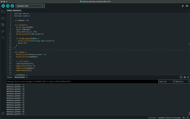
When all wired and configured, upload the sketch to the ESP32 and you should start seeing the ESP32 instruct the LoRa module to transmit the data:
Using adafruit-circuitpython-rfm9x with Raspberry Pi 4
This will be used for receiving data. Again, the instructions are the best place to start with this library. One thing the library doesn’t cover however is that you may need to enable SPI communication before using the SPI pins. Follow this guide to get that done.
I have my Pi set up for SSH, which I’d recommend for working with on things like this. There’s no need to attach a screen and keyboard - just SSH in from your local network and do all configuration from there.
Once installed, go to the library examples folder and copy the simpletest.py file to your Pi. Again, you’ll need to configure a couple of things.
First, the frequency:
RADIO_FREQ_MHZ = 433.0 # Frequency of the radio in Mhz. Must match yourThen the pins - here’s how I have mine wired up (diagram also below):
CS = digitalio.DigitalInOut(board.CE1)
RESET = digitalio.DigitalInOut(board.D25)
And finally a critical part which took me ages to figure out was that I had to set the with_header parameter when using the receive() function:
packet = rfm9x.receive(timeout=5.0,with_header=True)Without the with_header parameter, the first four characters of my message were always missing because the library was not expecting a header to be sent from the arduino-LoRa library, so didn’t know to leave space for it in the incoming buffer.
With all this in place, here’s the final code:
# SPDX-FileCopyrightText: 2021 ladyada for Adafruit Industries
# SPDX-License-Identifier: MIT

# Simple demo of sending and recieving data with the RFM95 LoRa radio.
# Author: Tony DiCola
import board
import busio
import digitalio

import adafruit_rfm9x


# Define radio parameters.
RADIO_FREQ_MHZ = 433.0  # Frequency of the radio in Mhz. Must match your
# module! Can be a value like 915.0, 433.0, etc.

# Define pins connected to the chip, use these if wiring up the breakout according to the guide:
CS = digitalio.DigitalInOut(board.CE1)
RESET = digitalio.DigitalInOut(board.D25)

# Initialize SPI bus.
spi = busio.SPI(board.SCK, MOSI=board.MOSI, MISO=board.MISO)

# Initialze RFM radio
rfm9x = adafruit_rfm9x.RFM9x(spi, CS, RESET, RADIO_FREQ_MHZ, baudrate=100000)

# Note that the radio is configured in LoRa mode so you can't control sync
# word, encryption, frequency deviation, or other settings!

# You can however adjust the transmit power (in dB).  The default is 13 dB but
# high power radios like the RFM95 can go up to 23 dB:
rfm9x.tx_power = 23

# Send a packet.  Note you can only send a packet up to 252 bytes in length.
# This is a limitation of the radio packet size, so if you need to send larger
# amounts of data you will need to break it into smaller send calls.  Each send
# call will wait for the previous one to finish before continuing.
rfm9x.send(bytes("Hello world!\r\n", "utf-8"))
print("Sent Hello World message!")

# Wait to receive packets.  Note that this library can't receive data at a fast
# rate, in fact it can only receive and process one 252 byte packet at a time.
# This means you should only use this for low bandwidth scenarios, like sending
# and receiving a single message at a time.
print("Waiting for packets...")

while True:
    #packet = rfm9x.receive()
    # Optionally change the receive timeout from its default of 0.5 seconds:
    packet = rfm9x.receive(timeout=5.0,with_header=True)
    # If no packet was received during the timeout then None is returned.
    if packet is None:
        # Packet has not been received
        print("Received nothing! Listening again...")
    else:
        # Received a packet!
        # Print out the raw bytes of the packet:
        print("Received (raw bytes): {0}".format(packet))
        # And decode to ASCII text and print it too.  Note that you always
        # receive raw bytes and need to convert to a text format like ASCII
        # if you intend to do string processing on your data.  Make sure the
        # sending side is sending ASCII data before you try to decode!
        packet_text = str(packet, "ascii")
        print("Received (ASCII): {0}".format(packet_text))
        # Also read the RSSI (signal strength) of the last received message and
        # print it.
        rssi = rfm9x.last_rssi
        print("Received signal strength: {0} dB".format(rssi))
Wiring the RFM9x module to the Raspberry Pi 4
Again, the wiring requires knowledge of the pins on the Raspberry Pi 4:
I originally got an error “RuntimeError: Failed to find rfm9x with expected version — check wiring”. I was debugging this for ages until I swapped out for a spare RFM98 module and everyhing started working right away. So this error could have been dodgy soldering, LoRa module, or wire connections for me, so give everything another look over.
Final connections are:
| RFM9x module | Pi 4 |
|---|---|
| VCC | 3.3V |
| GND | GND |
| SCK | SCLK/G11 |
| MISO | MISO/G9 |
| MOSI | MOSI/G10 |
| NSS/CS | CE1/G7 |
| NRESET | G25 |
| DIO0 | G5 |
Seeing the transmission in action
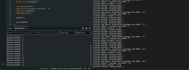
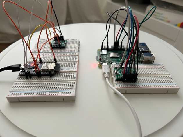
Once all set up, on your Pi run python3 [file].py to start listening for the transmissions from the ESP32. You should see the below:
With the two LoRa modules communicating only by radio:
Thanks for reading
I’m very new to this whole topic, and even though I’ve done a fair bit of research there’s still so much more I want to learn. This post has been the real basics, but I’ll be building on this in future posts as I work towards building something that is more thought out and useful. I’m writing these posts as I’m learning, so I’m not sure yet where I’ll end up.
Other useful links
- https://ukhas.org.uk/doku.php?id=guides:lora_tracking_guide
- https://learn.adafruit.com/lora-and-lorawan-radio-for-raspberry-pi
- https://learn.adafruit.com/adafruit-rfm69hcw-and-rfm96-rfm95-rfm98-lora-packet-padio-breakouts/overview
- https://www.hackster.io/news/what-wireless-communication-standard-to-use-for-your-next-project-2db9570eabaf
- https://randomnerdtutorials.com/esp32-lora-rfm95-transceiver-arduino-ide/
- https://circuitdigest.com/microcontroller-projects/arduino-lora-sx1278-interfacing-tutorial
Senior Engineer at Haven
