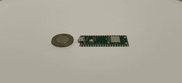
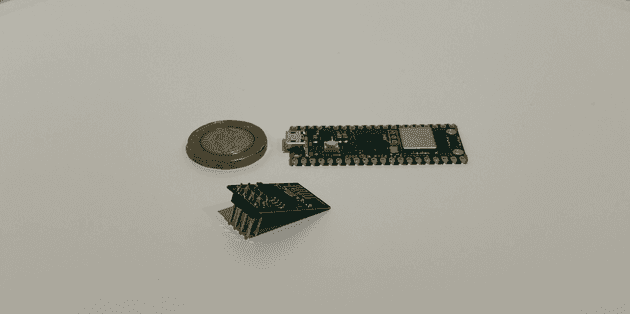
Creating a web server with the ESP-01 module connected to a Pi Pico
April 02, 2023
Image source: a wonderful creation by Dall-E
I’ve recently got back in to playing with electronics and IoT since reading up on High Altitude Balloons (HAB) which have been in the news recently. I’ve previously written about connecting the ESP8226 WiFi module to an Arduino, but I’ve recently wanted to connect the same module to a Raspberry Pi Pico, and ended up getting further into the weeds this time. I wanted to log my thoughts and progress as it required a lot of perseverance this time around.
What is a Raspberry Pi Pico
The Pico is the latest of Raspberry Pi’s boards. The company have recently released models such as the Raspberry Pi 4, or the Pi Computer Kit, which have all been essentially small computers. The Pico, however, is not a fully fledged £40 computer, but is a microcontroller.
At only £3.60 for one of these high performing little beauties, they are great for running all sorts of small IoT projects. My end goal is to use one in some sort of high altitude balloon flight, but after doing a bunch of research it’s safe to say it’s not going to happen over night.
I’ll do another post more specific to the HAB side of things after, but for now I wanted to document how I managed to get an ESP-01 WiFi module connected to my Pico.
What is an ESP-01, and why use it with a Pico
The ESP-01 is a small module which can be connected to a microcontroller board to give it access to the internet, or allow other devices to connect to it’s own network.
Raspberry Pi does actually have a version with WiFi capabilities out of the box, which still only costs £6.30 at time of writing, and I’ll definitely be getting one of those next time as it looks WAY easier to use both hardware and software wise. The ESP-01 WiFi module was a challenge to work with for a number of reasons which I’ll explain in this post.
The end goal of this post
With the HAB balloon stuff aside, my goal of connecting the ESP-01 to the Pico is to allow me to do the following:
- Connect ESP to Pico, and connect Pico to laptop
- Add program to the Pico to instruct it to communicate with the ESP and turn the ESP into a WiFi access point with it’s own network
- Connect my phone to the ESP’s own WiFi connection, and receive data from the Pico board directly to my phone’s web browser
The future goal (not covered in this post) is to connect other sensors to the Pico, such as temperature or GPS, and have the Pico relay that data via the ESP module, to my phone, all whilst been connected to battery.
Getting started to add the software
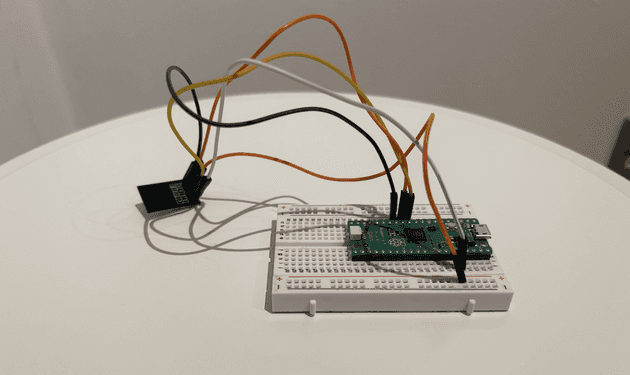
First thing to do is wire up the WiFi module to the Pico board:
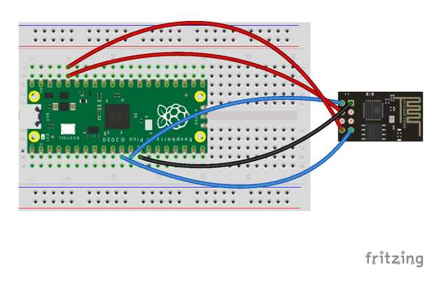
I’ve created an accompanying diagram to show clearer:
Connections (ESP > Pico):
- 3v3 > 3v3
- GND > GND
- EN > GND
- RX > TX
- TX > RX
Next is to get the Pico environment set up. Again, head on over to the Raspberry Pi site as they have an excellent, quick guide on how to do this (no need to do the LED stuff for this project though).
With Thonny installed and having used the shell and experienced the MicroPython language in the example, we can get to the good stuff.
Communicating with the ESP and understanding the AT firmware
This was one of the biggest problems for me, as I didn’t know anything about the ESP-01 firmware or how to work with it. In my previous post about adding WiFi capabilities to an Arduino with the ESP module, I touched on the ESP’s default firmware, AT, and how I decided to flash the ESP firmware and add my own code written in Arduino. This worked well for what I wanted at the time, but now I want to go back and learn how to use the ESP module using it’s pre-loaded firmware. Also this seems like an easier option when working with the Pico.
How to communicate with the ESP
We want to be able to configure the ESP module to do what we want, such as set the access point SSID and password. To do this, we send AT commands, as mentioned earlier. This was easy to do with Arduino because the Arduino software has a built in Arduino Serial Monitor to allow us to send commands directly to a specific serial port on the Arduino board. Thonny doesn’t have such features, but I found a good alternative that has helped me:
# serialMonitor.py

from machine import Pin, Timer, UART
import machine
import _thread
import time

uart = UART(1,baudrate=115200, tx=Pin(8), rx=Pin(9)) # add your own values

print('-- UART Serial --')
print('>', end='')

def uartSerialLogger():
    while True:
        command = uart.read(1)

        if command:
            recv=str(command.decode("utf-8"))
            print(recv, end='')

_thread.start_new_thread(uartSerialLogger, ())

while True:
    send = input()
    uart.write(send+'\r\n')
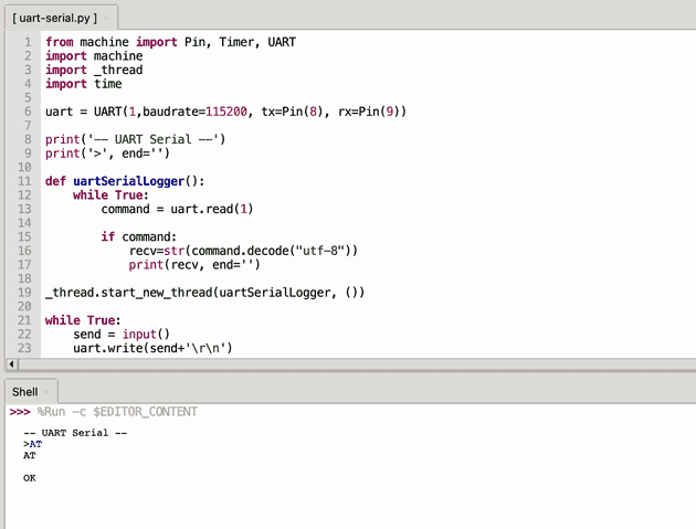
If you add the above code to your Pico, and run the file in Thonny, you will be able to use custom code to perform the action of sending commands, and receiving the responses. Note the UART() function which takes the parameters of serial port for the ESP module. For example:
At the bottom in the shell window, I’m sending the command AT, and we’re receiving the response OK. This is how we know the ESP module has the AT firmware installed, and that it’s functioning correctly.
It’s important to note that once the firmware is removed (or flashed), the ESP will no longer respond to AT commands. For example, I have a few of the ESP modules, one of which I used previously with my Arduino. I flashed it with my own code and tried to use it recently and it needed re-flashing. This great Instructables post explains how to flash the firmware back to the AT default if needed.
I did read that tools like
minicomare also a good point for sending/receiving data via serial port, but I didn’t venture down that route.
Understanding the AT firmware
As mentioned before, if you want to use the default AT firmware, you don’t add your own code to the ESP module. Instead you send commands to the ESP module to configure it to behave a certain way. There are great docs on the official manufacturers site (Espressif) which list all the commands you can send to the ESP module.
With this in mind, you can technically use the serial monitor code mentioned above, and configure the ESP module manually by sending configuration. For example, we can send the following command to set the ESP to use a custom SSID and password that devices can use to conned to the ESP:
AT+CWSAP="Pretty fly for a WiFi","wifi-password-123",3,0We could then send the following command to instruct the ESP to start running a web server on port 80:
AT+CIPSERVER=1,80We can then also send the following command to instruct the ESP to send a packet of 50 characters over WiFi to connection ID 0 (the data which the ESP sends will also need to be sent to the ESP in another message, but I’ll leave that out for now as it get’s complicated without more context).
AT+CIPSEND=0,50With all that in mind, it’s possible to configure the ESP this way, and it might be preferable in many situations, but when you want the ESP to behave as an internet-independent web server and send real-time data from the Pico board, it will be easier to do this in code.
Configuring the ESP with Micropython
Although I have brief experience with Python, this was the first time using the Micropython language, which is one of the three languages that can be used to program the Raspberry Pi Pico board (alongside C and C++). I tried to lift an example ESP configuration script from the web, but none of them worked as I wanted. Some of them didn’t seem to work at all, some of them were’nt flexible enough to allow me to easily add readings from other modules attached to the Pico, and some looked and worked great, but didn’t allow the ESP to be used as a standalone access point (instead, connecting ESP to an external WiFi connection to function).
I don’t mean to throw shade at those posts - I couldn’t get my server working because of my own lack of experience!
In the end I decided to bite the bullet and learn how the Micropython code works with the Pico and the ESP, and I’m glad that I did, as after a couple of nights I was able to debug problems properly and find a great solution for what I was after. I found a great repo on GitHub that didn’t have the functionality I wanted, but was a well constructed starting point to build on, so I forked it, added my own functionality, and began using!
My updated repo can be found here: https://github.com/jaygould/pico-micropython-esp8266-lib.
The esp8266.py file contains the functionality in the form of a library. I added the ability to set the ESP as an access point, return the IP address to access in the browser, start the web server, and also serve the content. The challenging part was serving the content:
    def listenForConnections(self):
        print('Listening for connections...')

        while True:
            receivedConnectionData = ""

            self.__rxData=bytes()
            while self.__uartObj.any()>0:
                self.__rxData += self.__uartObj.read(1)

            receivedConnectionData = self.__rxData.decode('utf-8')

            time.sleep(2)

            if '+IPD' in receivedConnectionData: # if a connection is found, respond with HTML
                id_index = receivedConnectionData.find('+IPD')
                connection_id =  receivedConnectionData[id_index+5]

                pageContent = self.getPageContent()
                pageContentLength = len(pageContent)
                pageWrapLength = 97
                totalPageLength = str(pageContentLength + pageWrapLength)

                self._sendToESP8266('AT+CIPSEND='+connection_id+','+totalPageLength+''+'\r\n')
                time.sleep(1)
                self.__uartObj.write('HTTP/1.1 200 OK'+'\r\n')
                self.__uartObj.write('Content-Type: text/html'+'\r\n')
                self.__uartObj.write('Connection: close'+'\r\n')
                self.__uartObj.write(''+'\r\n')
                self.__uartObj.write('<!DOCTYPE HTML>'+'\r\n')
                self.__uartObj.write('<html>'+'\r\n')
                self.__uartObj.write('<body>'+'\r\n')
                self.__uartObj.write(pageContent+'\r\n')
                self.__uartObj.write('</body></html>'+'\r\n')
                time.sleep(2)
                self._sendToESP8266('AT+CIPCLOSE='+ connection_id+'\r\n')
                time.sleep(2)

                print("Waiting for connection")

    def getPageContent(self):
        return 'This is the page content :) woohoo'
The code runs on the Raspberry Pi Pico of course, because the ESP is only receiving instructions over the UART channel.
The while True: is a constantly running loop, and within that loop the following section listens for data coming in from the ESP to the Pico:
    self.__rxData=bytes()
    while self.__uartObj.any()>0:
        self.__rxData += self.__uartObj.read(1)
When all the incoming data is contained in self.__rxData, we decode it and assign it to a variable:
receivedConnectionData = self.__rxData.decode('utf-8')Incoming data from the ESP could be anything - an error message, an automated request to the Pico etc… but we are interested in WiFi connections being made to the ESP:
if '+IPD' in receivedConnectionData: # if a connection is foundWithin that if statement, we identify the connection ID making the request (which can be one of the 5 possible connections accessing the ESP at any one time), and instruct the ESP to start sending HTML content to that connection ID:
    self._sendToESP8266('AT+CIPSEND='+connection_id+','+totalPageLength+''+'\r\n')
    time.sleep(1)
    self.__uartObj.write('HTTP/1.1 200 OK'+'\r\n')
    self.__uartObj.write('Content-Type: text/html'+'\r\n')
    self.__uartObj.write('Connection: close'+'\r\n')
    self.__uartObj.write(''+'\r\n')
    self.__uartObj.write('<!DOCTYPE HTML>'+'\r\n')
    self.__uartObj.write('<html>'+'\r\n')
    self.__uartObj.write('<body>'+'\r\n')
    self.__uartObj.write(pageContent+'\r\n')
    self.__uartObj.write('</body></html>'+'\r\n')
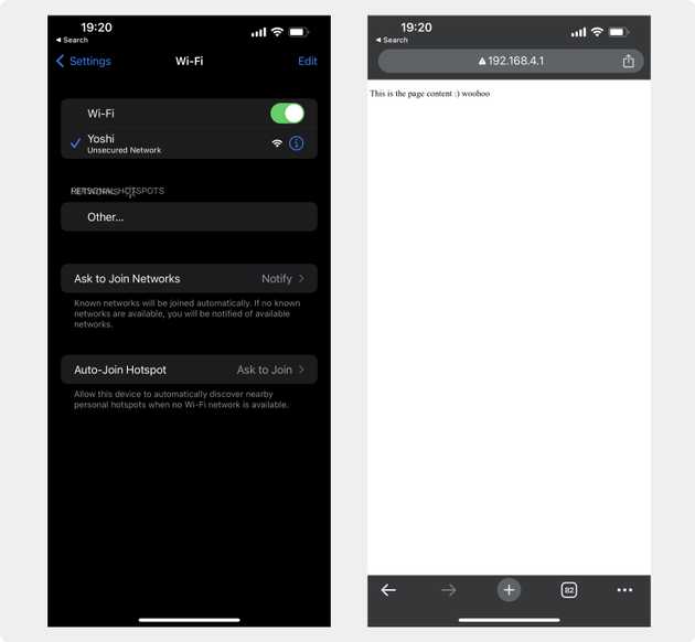
With all that in place, and the ESP and Pico connected and powered, I’m able to connect to the ESP’s WiFi network, and access the server I configured to receive the content:
Future improvements
The end goal is to get the ESP serve data specific to other components connected to my Pico. Ideally sensor data like the temperature and humidity, and even better - GPS data to get the location of the board. This is going to be made much easier now I have a better understanding of how the ESP connects to the Pico, how to send/receive data, and how to write the code on the Pico to bring it all together.
Senior Engineer at Haven

