Control Arduino board over the internet with ESP8226 WiFi
January 25, 2021
Last year during lockdown V1 I’d purchased the Arduino Starter Kit and posted my experience of the first week’s usage. Following the starter kit project book is a great introduction to the world of electronics for those of us who haven’t thought about voltage and resistance since year 11 GCSEs, but it’s uninspiring for a web developer who wants to jump into connecting their electronics to the web. When lockdown V3 recently hit, I decided to blow the dust off my Arduino kit and do something fun with it. This post shows how I used Arduino to create a web server at home to connect to electronic devices, hosted solely on a tiny microcontroller.
Setting up a web server is a piece of cake for developers who have been in the industry for a while, but perhaps not outside the comfort of an AWS or hosting provider dashboard, which is why I’m going to cover a lot of the basics here. There are loads of posts out there which do a poor job at explaining what’s needed for what seems like a trivial setup!
Arduino Uno features
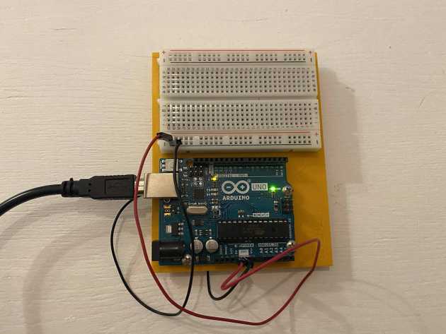
I’d purchased the Arduino Uno Rev 3 for this project. Actually that Arduino board came in the Arduino Starter Kit along with a load of other components such as LEDs, resistors, buttons, and much more. The starter kit has 15 projects in total, ranging from basics like turning on an LED with the push of a button, all the way up to turning motors and running on batteries to make the Arduino board portable.
The projects are great, but there’s one thing missing - connectivity. As standard, the Arduino Uno Rev 3 does not have the ability to communicate with anything other than the computer which is programming it. When the Uno is unplugged from the computer, it can’t connect to anything at all. There’s an Arduino Uno Rev 2 WiFi available, but this doesn’t seem as popular and doesn’t come in the starter kit.
The ESP8226-01 module
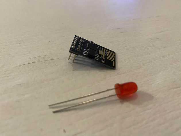
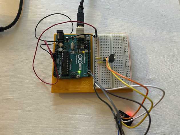
Luckily, the electronics world is huge and there seems to be a component for everything, including a load of WiFi modules that can be connected to an Arduino Uno, giving the Uno opportunities for making more exciting projects. One such module is the ESP8226 (ESP-01 for short), a powerful and incredibly popular component providing WiFi connectivity to things like the Arduino, as well as other electronic components like the NodeMCU ESP8226 module. This is what the ESP8226-01 looks like:
From a web developer’s point of view, this is really exciting because the power of the web can be used to affect anything the Arduino can do, including making a web server to control an Arduino board from anywhere in the world, embedded in an exciting Javscript project, for example.
What you’ll learn in this post
This post covers the following:
- How to use the Arduino IDE to program the ESP-01
- Connecting the ESP-01 to an Arduino Uno
- Turning the ESP-01 in to a web server
- Allowing the ESP-01 and Arduino Uno to transfer data using Serial communication
The end result will be allowing the Arduino Uno to use the power of WiFi to receive commands from a web browser (served by the ESP-01) and updating components attached to the Uno based on server responses.
What you’ll need
When I was first looking in to adding WiFi to my Arduino Uno, I was surprised at how many posts didn’t give basic information like what components are actually needed. That’s why I’m listing everything you’ll need to get this done:
- Arduino Uno
- ESP-01 - this link is the one I used to buy, but really any ESP-01 device will do as they are all the same
- 3.3v Voltage Regulator
- Breadboard
- Jumper cables
- USB cable to power the Arduino
It’s important that the ESP-01 is not fed a full 5V from the Arduino’s 5V pin out. Apparently this is meant to fry the ESP chip, although I’ve not expierienced this myself. I’ve tried feeding the ESP-01 with the 3.3V pin from the Arduino, but this didn’t seem to power it correctly and meant it was turning off and on all the time. That’s why the voltage regulator is required. This component ensures that 3.3V is output from itself when a higher voltage is supplied, such as the 5V from the Arduino.
Installing ESP8226 libraries on Arduino IDE
The default installation of Arduino IDE includes a few basic libraries and example sketches to interface with the Arduino, but you can also install various other packages. In order for us to be able to program the ESP-01 using the Arduino IDE, we need to install the ESP8226 package.
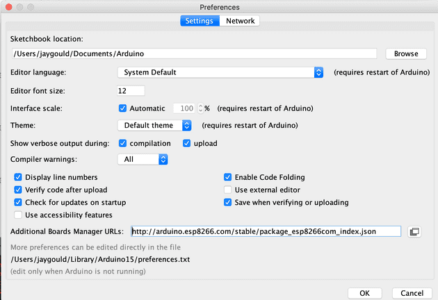
Go to Arduino > Preferences and add the following URL to the Additional Boards Manager URLs field:
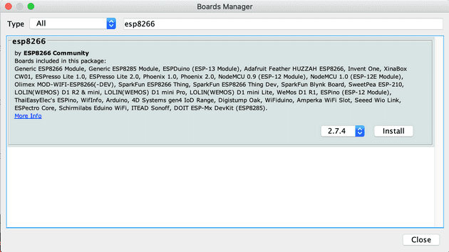
http://arduino.esp8266.com/stable/package_esp8266com_index.jsonClick OK, then go to Tools > Board > Boards Manager, and type in “ESP8226” in to the input field. There should be the ESP8226 package - click install, and once finished, close the window.
The Arduino IDE now has access to libraries such as WiFi, server hosting, HTTP processes and loads more.
Programming the ESP8226 to be a web server using Arduino IDE
By default the ESP8226 comes loaded with AT Firmware, which is a standard way to interface with the ESP-01 to do things like connect to a specific WiFi router, and send/receive requests to/from URLs, all using the serial window in the Arduino IDE. I tried it and thought it was a clunky way to work. Fortunately, we’re able to overwrite the standard AT firmware, replacing it with our own code. I prefer to do everything with my own code as it feels more natural coming from a web dev background.
Loading code on to an ESP-01 can be complicated, with people giving solutions involving USB-to-TTL converters, separate power supplies, a bunch of resistors, and that’s just to load code on to the ESP! If you have an Arduino there’s no need for any of that as we can use the Uno’s built-in USB to serial converter. This allows our program to go from the computer, through USB, and then through the Arduino’s serial pins in to the ESP-01.
Important: before continuing, please upload the “Blink” sketch on to the Arduino Uno. This ensures there’s no Serial communication happening on the Arduino. Serial communication is data transfer which happens when components are communicating, with use of code such as Serial.print() as you may have seen if you’ve done some projects in the starter kit, which in the project book is communication between the Uno and our computer. In order to program our ESP-01, we’ll be using the Serial data stream running through the Arduino, so this stream needs to be empty.
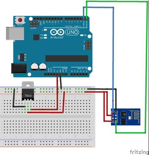
Start off by connecting the ESP-01 to the Arduino:
The connections are:
- ESP GND -> ARDUINO ground
- ESP VCC/3V3 -> ARDUINO 3.3V from regulator
- ESP CHPD/EN -> ARDUINO 3.3V from regulator
- ESP RX -> ARDUINO RX (pin 0)
- ESP TX -> ARDUINO TX (pin 1)
- ESP GPIO0 -> ARDUINO ground
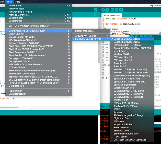
Then select the correct board in Arduino IDE, which is the “Generic ESP8226 Module”:
Selecting this board is required so our program can access includes from the ESP8226 package we added earlier.
Finally, create a sketch with the following code:
#include <ESP8266WiFi.h>
#include <ESP8266WebServer.h>

ESP8266WebServer server(80);

const char* ssid = "your-router-name";
const char* password = "your-router-password";

void setup() {
  Serial.begin(9600);
  delay(10);
  Serial.println('\n');

  connectWifi();
  setupServer();
}

void loop() {
  server.handleClient();
  delay(100);
}

void connectWifi() {
  WiFi.begin(ssid, password);
  Serial.print("Connecting to ");
  Serial.print(ssid); Serial.println(" ...");

  int i = 0;
  // Wait for the Wi-Fi to connect
  while (WiFi.status() != WL_CONNECTED) {
    delay(1000);
    Serial.print(++i); Serial.print(' ');
  }

  Serial.println('\n');
  Serial.println("Connected :)");
  Serial.print("IP address:\t");
  Serial.println(WiFi.localIP());
}

void setupServer() {
  server.on ("/", serverRoot);
  server.begin();
  Serial.println ("HTTP server started");
  server.on("/TURN_LED_ON", []() {
    Serial.print("1");
    delay(1000);
    serverRoot();
  });
  server.on("/TURN_LED_OFF", []() {
    Serial.print("0");
    delay(1000);
    serverRoot();
  });
}

void serverRoot() {
  server.send(200, "text/html", "<form action=\"/TURN_LED_ON\" method=\"get\"><button type=\"submit\" value=\"On\">On</button></form><form action=\"/TURN_LED_OFF\" method=\"get\"><button type=\"submit\" value=\"Off\">Off</button></form>");
}
There’s a lot going on in the sketch but I’ve tried to keep it as simple as possible. It’s using the ESP8226 libraries to set up a web server, along with server routes, and sending server response via an HTTP response. The response is HTML containing an on and off button, which when clicked, will tell the ESP to run Serial.print();.
Now if you try and upload this sketch, it will fail because the ESP-01 is not in “programming mode” (a term I just made up). This is where it gets a bit complicated, and where other posts don’t explain enough for beginners. In order to enable the ESP to receive code (flash the ESP), you need to add the RST pin on the ESP-01 to ground on the Arduino for half a second or so.
Basically just put it in and take it out. This resets the ESP-01, and only works when GPIO0 on the ESP is wired to ground on the Arduino.
Once that’s been done, you’ll see the blue light on the ESP-01 flash a little, and it’s now ready to press upload in the Arduino IDE. Without doing the RST wire process, you’ll likely get a “Timed out waiting for packet header” error:
If you have trouble uploading, try doing the RST wire tap process a second time after the program has finished compiling, as the debug window shows “Connecting…“.
Once uploaded, the ESP-01 needs to be taken out of “programming mode” and allowed to run it’s normal process as a microcontroller, which in our case is connecting to our local WiFi, and setting up a web server. To do this simply remove the GPIO0 pin out of the breadboard, and add the RST pin on the ESP-01 to ground for half a second again (like earlier).
To test this is working, open the serial monitor with Tools > Serial Monitor and set the baud rate to 9600 to match the baud rate declared in the setup function of our code. This will allow you to see the Serial output provided by the code on the ESP. If you can’t see anything, try doing the RST wire tap process one more time with the serial window open.
It’s a little confusing when you first fiddle around with the wires, so I’ll summarise here:
- Ensure the Uno has a blank sketch like Blink installed so there’s no active serial comms
- Connect the ESP-01 to the Arduino as per the diagram and text above
- Ensure the Generic ESP8226 Module board is selected in IDE
- Take the RST wire going from ESP and briefly tap the ground on the Arduino breadboard
- Upload the sketch (possibly do the RST wire tap again while connecting if transfer doesn’t happen)
- Open serial monitor
- Take GPIO0 wire out of the Arduino breadboard, and do the RST wire tap again
If all goes smoothly, you should see serial output of the WiFi connecting, and listing the IP address of your dope new server. Go to the IP address in your browser to see the site, press the buttons, and see the button output back in the Arduino serial monitor. This is great because you’re using a different machine to send instructions to the ESP-01 module over WiFi!
Although this is some sick tech setup, the ESP-01 is kind of just acting on it’s own at the moment, and not communicating with the Arduino Uno. The Uno has played an important part in being a USB to serial converter, allowing us to upload code to the ESP, but what we really want is for the Uno to turn on an LED based on data coming in from the ESP-01.
Transferring data between the ESP-01 and Arduino Uno
Now the ESP-01 is a server, we want the Uno to receive the data from the server telling the circuit board about the button clicks on our website. This is all done with serial data transfer, which is the code already used on the ESP (such as the Serial.print() function).
So far the Uno should have the Blink sketch loaded on so the serial data connection was freed up for the ESP program transfer earlier. We want to take out the RX and TX wires out of the Uno, as these will interrupt the loading of our Uno program.
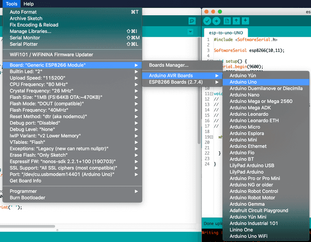
Go to Tools > Board > Arduino Boards and select Arduino Uno. This ensures our program is being uploaded to the Uno, and that the program has access to the correct libraries:
Then create a new sketch and upload to the Uno:
#include <SoftwareSerial.h>

SoftwareSerial esp8226(10,11); // (RX, TX)

void setup() {
  Serial.begin(9600);
  esp8226.begin(9600);

}

void loop() {
  while(esp8226.available()) {
    Serial.write(esp8226.read());
    delay(100);
  }
}
The sketch uses a popular library called “SoftwareSerial”, which allows the Uno to receive the data from the ESP over custom pins. The default pins for serial data transfer on the Uno are pins 0 (RX, or receive) and 1 (TX, or transfer), but these default pins on the Uno are linked to the standard Serial.print(), Serial.read() etc. functions. We want to be able to use the Uno’s standard serial output so we can debug on our computer, so the SoftwareSerial allows other pins to be used to send/receive data over serial connection. Our code assigns the data coming in from ESP to the Uno to run through pins 10 and 11.
With that in mind, update the wiring to reflect the serial setup:
- ESP GND -> ARDUINO ground
- ESP VCC/3V3 -> ARDUINO 3.3V from regulator
- ESP CHPD/EN -> ARDUINO 3.3V from regulator
- ESP RX -> ARDUINO software serial TX (pin 11)
- ESP TX -> ARDUINO software serial RX (pin 10)
Note how RX goes to TX and vice versa. This is because we’re setting the ESP-01 and Uno to communicate to one another, whereas before we were simply using the Uno as a USB to serial connection and passing the data right through to the corresponding pins. Also the ESP GPIO0 is no longer connected, as that’s only needed for flashing the ESP.
With access to the esp8226 SoftwareSerial connection, the Arduino can listen to that in the loop, and write to the Uno’s serial output, which is the serial window on our computer. So basically the data goes from ESP -> Uno (via SoftwareSerial) -> our computer serial window (via standard Uno serial).
To confirm this is working, open the serial monitor, which is now the serial data coming from the Uno and not the ESP (due to the ESP serial wires now in other pins), and press a button in the web browser. The “0” or “1” response should appear, and if you do the good ol’ RST trick with the ESP (putting RST wire to Arduino ground for a moment), the Uno serial will output the initial WiFi connection output from the ESP. Magic!
Controlling Arduino Uno circuit components with ESP8226
Now we’re successfully sending data between the ESP-01 and Uno, we can control the components connected to the Arduino like you would do normally. In this post I’ll show a simple LED turning on and off:
#include <SoftwareSerial.h>

SoftwareSerial esp8266(10,11);

const int ledPin = 12;
int data;

void setup() {
  Serial.begin(9600);
  esp8266.begin(9600);

  pinMode(ledPin, OUTPUT);}

void loop() {
  while(esp8266.available()) {
    data = esp8266.read();
    Serial.write(data);

    if(data == '1') {      digitalWrite(ledPin, HIGH);    }    if(data == '0') {      digitalWrite(ledPin, LOW);    }
    delay(100);
  }
}
Once this is uploaded to the Uno, simply use the buttons on the website served from the ESP and the LED is toggled using the digitalWrite() command.
Making changes to the ESP-01 program
When you need to go back and change the ESP-01 code, be sure to follow the same steps as mentioned earlier to enter the ESP in to programming mode:
- Move the serial pins going to the Arduino from pins 10 and 11 to the original TX -> TX and RX -> RX
- Attach the GPIO0 wire to ground on the Uno
- Do the RST flash tap to Arduino ground (and again while connecting if it doesn’t work)
And be sure to reverse that process when putting the ESP back in normal running mode.
You may want to update the ESP for many reasons, as the possibilities of using Arduino has opened up massively!
A few gotchas when making more complex projects
One thing to note is that the serial communication between components happens by transferring one byte at a time (meaning one character). This means you can’t send a whole string from the ESP to the Uno in one go. I use this solution on Stack Exchange to get around this issue when the Uno needs more than just a single digit to perform an action.
Throughout this post the Uno has been powered by the laptop/computer via USB connection, but your IoT project only really comes to life when it’s able to work with its own power source. One option for this is to plug the Arduino USB cable in to a mobile phone charger as these supply the right voltage (5V) using the charger’s inner voltage regulation. Be sure not to connect to full 110 or 230 volts from home power sockets directly and use a 5V USB plug!
Another power source could be batteries - either a 9V square battery span, or even a battery pack which takes a series of AA batteries. It can get complicated when using batteries when trying to get components to run on a single charge for a long time, but that post is for another time! Be sure to look up how to use these correctly though, as you shouldn’t supply too much voltage to components.
## Alternatives to using ESP-01
For beginners like me, it was quite the ordeal getting this working as there was so much to learn. Hopefully this has helped anyone wanting to do the same thing, but it’s worth mentioning that there are alternatives, some arguably better than this setup. Even though the ESP-01 component is rediculously cheap, it can function on it’s own without the Arduino. Of course, this would mean setting up a separate 3.3V power supply to feed the ESP, and the ESP only has 2 GPIO pins, meaning you can only connect 2 components to a circuit. Having an Arduino allows many pins, as well as analog pins too!
Another solution is to use another board entirely, such as the NodeMCU ESP8226. This has built in WiFi ESP component, a good amount of memory, and a load of GPIO pins, meaning it can replace the Arduino Uno completely and pretty much save all the hassle of serial communication I’ve gone in to here. I have a few myself, but I like the idea of having the Uno connected to WiFi for any future projects I might want to use the Uno for.
Want to know more about the ESP8226?
As I was getting to grips with the ESP-01, I struggled to find decent content on the web explaining things well. One of the very few sites I loved though was the Pieter’s Github page, so if you want a more rounded, detailed run down of the ESP8226, this is the place to start.
Where to go from here
Like I said before, you can do so much with this basic(ish) understanding of serial communication between the Arduino Uno and WiFi components. With all the other things to connect to the Uno such as temperature sensors, light sensors, LCD screens, speakers etc, you can make some awesome IoT solutions. If you’re a web developer you can even throw in some knowledge with WebSockets, web hooks, API calls to things like Alexa or Google.
Senior Engineer at Haven
